What is Canal Fall?
Irrigation canals are constructed with some permissible bed slopes so that there is no silting or scouring in the canal bed. But it is not always possible to run the canal at the desired bed slope throughout the alignment due to the fluctuating nature of the country slope. Generally, the slope of the natural ground surface is not uniform throughout the alignment. Sometimes, the ground surface may be steep, and sometimes it may be very irregular with an abrupt change of grade. In such cases, a vertical drop is provided to step down the canal bed, and then it is continued with a permissible slope until another step down is necessary. This is done to avoid unnecessary huge earthwork in filling. Such vertical drops are known as canal falls or simply falls.
The necessity of Canal Falls:
o When the slope of the ground suddenly changes to steeper slope, the permissible bed slope can not be maintained. It requires excessive earthwork in filling to maintain the slope. In such a case falls are provided to avoid excessive earth work in filling
 |
| necesity of cannel fall |
o When the slope of the ground is more or less uniform and the slope is greater than the permissible bed slope of canal. In that case also the canal falls are necessary.
o In cross-drainage works, when the difference between bed level of canal and that of drainage is small or when the F.S.L of the canal is above the bed level of drainage then the canal fall is necessary to carry the canal water below the stream or drainage.
 |
| Types of Canal Falls |
Types of Canal Falls
The following are the different types of canal falls that may be adopted according to the site condition:
Ogee Fall
In this type of fall, an ogee curve (a combination of convex curve and concave curve) is provided for
carrying the canal water from a higher level to a lower level. This fall is recommended when the natural
ground surface suddenly changes to a steeper slope along the alignment of the canal.
o The fall consists of a concrete vertical wall and concrete bed.
o Over the concrete bed the rubble masonry is provided in the shape of an ogee curve.
o The surface of the masonry is finished with rich cement mortar (1:3).
o The upstream and downstream side of the fall is protected by stone pitching with cement grouting.
o The design consideration of the ogee fall depends on the site condition.
 |
| ogee fall |
Rapid Fall
The rapid fall is suitable when the slope of the natural ground surface is even and long. It consists of a
long sloping glacis with a longitudinal slope which varies from 1 in 10 to 1 in 20.
o Curtain walls are provided on the upstream and downstream sides of the sloping glacis.
o The sloping bed is provided with rubble masonry.
o The upstream and downstream side of the fall is also protected by rubble masonry.
o The masonry surface is finished with rich cement mortar
 |
| Rapid fall |
Stepped Fall
Stepped fall consists of a series of vertical drops in the form of steps. This fall is suitable in places
where the sloping ground is very long and requires long glacis to connect the higher bed level with the lower bed level.
o This fall is practically a modification of the rapid fall.
o The sloping glacis is divided into a number of drops so that the flowing water may not cause any
damage to the canal bed. Brick walls are provided at each of the drops.
o The bed of the canal within the fall is protected by rubble masonry with surface finishing by rich
cement mortar (1:3).
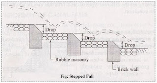 |
| Stepped fall |
Trapezoidal Notch Fall
In this type of fall a body wall is constructed across the canal. The body wall consists of several
trapezoidal notches between the side piers and the intermediate pier or piers. The sills of the notches are
kept at the upstream bed level of the canal.
o The body wall is constructed with masonry or concrete.
o An impervious floor is provided to resist the scoring effect of the falling water.
o The upstream and downstream side of the fall is protected by stone pitching finished by cement
grouting.
o The size and number of notches depends upon the full supply discharge of the canal.
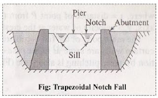 |
| Trapezoidal Notch Fall |
Vertical Drop Fall
It consists of vertical drop walls which is constructed with masonry work. The water flows over the
crest of the wall. A water eastern is provided on the downstream side which acts as a water cushion to
dissipate the energy of falling water.
o A concrete floor is provided on the downstream side to control the scouring effect of the flowing
water.
o Curtain walls are provided on the upstream and downstream side.
o Stone pitching with cement grouting is provided on the upstream and downstream side of the fall
to protect it from scouring.
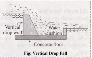 |
| Vertical Drop Fall |
Glacis Fall
It consists of a straight sloping glacis provided with a crest. A water cushion is provided on the
downstream side to dissipate the energy of flowing water.
o The sloping glacis is constructed with cement concrete.
o Curtain walls and toe walls are provided on the upstream and downstream side.
o The space between the toe walls and curtain walls is protected by stone pitching.
o This type of fall is suitable for drops up to 1.5 m.
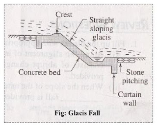 |
| Glacis Fall |
For the improvement in energy dissipation, the glacis falls have been modified as follows:
(a) Montague Type Fall
In this type of fall, the straight sloping glacis is modified by giving a parabolic shape which is known
as the Montague profile. Taking “0” as the origin, the Montague profile is given by the equation,
X = υ √4 y/g+ Y
Where x = distance of point P from OX axis,
Y = distance of point P from OY axis,
υ = velocity of water at the crest,
g = acceleration due to gravity
 |
Montague Type Fall |
The main body of the fall is constructed with cement concrete. Toe walls and curtain walls are same
as in the case of straight sloping glacis. The bed protection by stone pitching is also same.
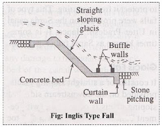
(b) Inglis Type Fall
In this type of fall, the gracis is straight and sloping, but buffle walls are provided on the
downstream floor to dissipate the energy of flowing water.
o The height of buffle depends on the head of water on the upstream side.
o The main body of the fall is constructed with cement concrete.
o The toe walls and curtain walls are same as straight glacis.
o The protection works with stone pitching are also same. Sometimes, this fall is known as
buffle fall.
 |
| Inglis Type Fall |
Canal Regulators
 |
| Canal Regulators |
A head regulator provided at the head of the off-taking channel, controls the flow of water entering the
new channel. While a cross regulator may be required in the main channel downstream of the off-taking channel and is operated when necessary so as to head up water on its upstream side, thus to ensure the required supply in the off-taking channel even during the periods of low flow in the main channel.
Main functions of a head regulator:
To regulate or control the supplies entering the off-taking canal
To control the entry of silt into the off-taking canal
To serve as a meter for measuring discharge.
Main functions of a cross regulator:
To control the entire Canal Irrigation System.
To help in heading up water on the upstream side and to fed the off-taking canals to their full
demand.
To help in absorbing fluctuations in various sections of the canal system, and in preventing the
possibilities of breaches in the tail reaches.
Cross regulator is often combined with bridges and falls if required.
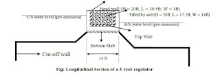
Typical Layout and Cross-section of a regulator |
| Typical Layout and Cross-section of a regulator |
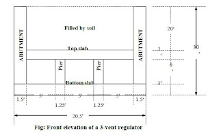 |
| Front elevation of a 3-vent regulator |
Canal Escapes:
It is a side-channel constructed to remove surplus water from an irrigation channel (main canal, branch
canal, or distributary etc.) into a natural drain.
The water in the irrigation channel may become surplus due to -
Mistake
Difficulty in regulation at the head
Excessive rainfall in the upper reaches
Outlets being closed by cultivators as they find the demand of water is over
Canal escapes act as safety valves in case of accidental breaches.
Types of Canal Escapes:
(a) Weir type escape:
 |
| Weir type escape |
Crest level = FSL of the canal
Water escapes if wL > FSL
The crest of the weir wall is kept at R.L equal to canal FSL. When the water level rises above FSL, it gets
escaped.
(b) Regulator/sluice type escape: |
| Regulator or sluice type escape |
The silt of the escape is kept at canal bed level and the flow can be used for completely
emptying the canal.
They may be constructed for the purpose of scouring off excess bed silt deposited in the head
reaches from time to time.
Canal Outlets/Modules:
A canal outlet or a module is a small structure built at the head of the watercourse so as to connect it
with a minor or a distributary channel.
It acts as a connecting link between the system manager and the farmers.
Requirements of a good module:
It should fit well to the decided principles of water distribution.
It should be simple to construct.
It should work efficiently with a small working head.
It should be cheaper.
It should be sufficiently strong with no moving parts, thus avoiding periodic maintenance.
It should e such as to avoid interference by cultivators.
It should draw its fair share of silt.
Types of outlets/modules:
(a) Non-modular module:
Non-modular modules are those through which the discharge depends upon the head difference
between the distributary and the watercourse.
Common examples are:
(i) Open sluice
(ii) Drowned pipe outlet
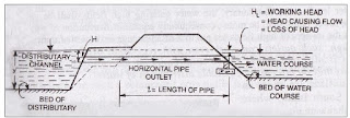 |
| Non-modular module |
Lowering of the bed of the watercourse will draw extra discharge. Thus the equitable distribution of
discharge may not be possible.
(b) Semi-modules or Flexible modules:
Due to construction, a super-critical velocity is ensured in the throat and thereby allowing the
formation of a jump in the expanding flume.
The formation of hydraulic jump makes the outlet discharge independent of the water level in
the watercourse, thus making it a semi-module.
Semi-modules or flexible modules are those through which the discharge is independent of the
water level of the watercourse but depends only upon the water level of the distributary so long as
a minimum working head is available.
Examples are pipe outlet, open flume type etc.
(c) Rigid modules or Modular Outlets:
Rigid modules or modular outlets are those through which discharge is constant and fixed within
limits, irrespective of the fluctuations of the water levels of either the distributary or of the water
course or both.
An example is Gibb’s module:
 |
| Gibb’s Module |
READ MORE:




No comments:
Post a Comment
If you are getting more information from civilengineerfriend page please give your comments. Share the page information in your whatsapp group. Subscribe our page to get more information.