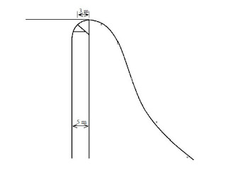
Spillway:
The spillways are openings provided at the body of the dam to discharge safely the excess water or flood water when the water level rises above the normal pool level.
Necessity of Spillways
(a) The height of the dam is always fixed according to the maximum reservoir capacity. The normal pool level indicates the maximum capacity of the reservoir. The water is never stored in the reservoir above this level. The dam may fail by overturning so, for the safety of the dam the spillways are essential.
(b) The top of the dam is generally utilized by making roads. The surplus water is not be allowed to overtop the dam, so to stop the overtopping by the surplus water, the spillways become extremely essential.
(c) To protect the downstream base and floor of the dam from the effect of scouring and erosion, the spillways are provided so that the excess water flows smoothly. Location of Spillway Generally, the spillways are provided at the following places
o Spillways may be provided within the body of the dam.
o Spillways may sometimes be provided at one side or both sides of the dam.
o Sometimes by-pass spillway is provided which is completely separate from the dam.
Determination of discharge capacity and number of spillways The maximum discharge capacity and the number of spillways are determined by studying the
following factors:
(a) By studying the flood hydrograph of the past ten years, the maximum flood discharge may be computed which is to be disposed of completely through the spillways.
(b) The water level in the reservoir should never be allowed to rise above the maximum pool level and should remain at the normal pool level. So, the volume of water collected between maximum pool level and minimum pool level computed, which indicates the discharge capacity of spillways.
(c) The maximum flood discharge may also be computed from other investigations like rainfall records, flood routing, empirical flood discharge formulae, etc.
(d) From the above factors the highest flood discharge is ascertained to fix the discharge capacity of spillways.
(e) The natural calamities are beyond the grip of human beings. So, an allowance of about 25 % should be given to the computed highest flood discharge which is to be disposed of.
(f) The size and number of spillways are designed according to the design discharge.
Types of Spillways
(a) Drop Spillways
(b) Ogee Spillway
(c) Siphon Spillway
(d) Chute or Trough Spillway
(e) Shaft Spillway
(f) Side Channel Spillway
(a) Drop Spillway
In the drop spillway, the overflowing waterfalls freely and almost vertically on the downstream side of the hydraulic structure. This type of spillway is suitable for weirs or low dams. The crest of the spillway is provided with a nose so that the water jet may not strike the downstream base of the structure. To protect the structure from the effect of scouring horizontal impervious apron should be provided on the downstream side. Sometimes a basin is constructed on the downstream side to form a small artificial pool which is known as a water cushion. This cushion serves the purpose of energy dissipating.
 |
| Drop Spillway |
(b) Ogee Spillways
The ogee spillway is a modified form of drop spillway. Here, the downstream profile of the spillway is made to coincide with the shape of the lower nappe of the free-falling waterjet from a sharp-crested weir. In this case, the shape of the lower nappe is similar to a projectile and hence the downstream surface of the ogee spillway will follow the parabolic path where “0” is the origin of the parabola. The downstream face of the spillway forms a concave curve from a point “T” and meets with the downstream floor. This point “T” is known as point of tangency. Thus the spillway takes the shape of the letter “S” (i.e. elongated form). Hence, this spillway is termed as ogee spillway.
 |
| Ogee Spillways |
 |
| The value of K and n are given as follow |
What
is Canal Fall?The necessity of Canal Falls and Types of Canal Falls
What
are cross drainage works? Types of Cross-Drainage Works
Spillway and Necessity of Spillways
Dams and Different parts & terminologies of Dams?
Divide wall and main function
The layout of a Diversion Head Works and its components


No comments:
Post a Comment
If you are getting more information from civilengineerfriend page please give your comments. Share the page information in your whatsapp group. Subscribe our page to get more information.