Dams
A dam is a hydraulic structure of fairly impervious material built across a river to create a reservoir on its upstream side for impounding water for various purposes. These purposes may be Irrigation, Hydropower, Water-supply, Flood Control, Navigation, Fishing, and Recreation. Dams may be built to meet the one of the above purposes or they may be constructed fulfilling more than one. As such, Dam can be classified as Single-purpose and Multipurpose Dam.
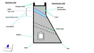
Different parts & terminologies of Dams:
Various types of dams
Based on the functions of dam, it can be classified as follows:
Based on structure and design, dams can be classified as follows:
 |
| Mohale dam, Lesoto Africa. |
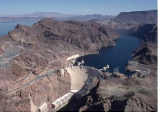 |
| Hoover Dam, USA |
 |
| buttress dam |
 |
| steel dam |
 |
| Timber dam |
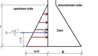 |
| Upstream face of the dam is vertical and there is no water on the downstream side of the dam |
Figure 1
The total pressure is in horizontal direction and acts on the
upstream face
at a height H/3 from the bottom.
The pressure diagram is triangular and
the total pressure is given by P1=wH^2/2
Where w is the specific weight of water. Usually it is taken as
unity.
H is the height upto which water is stored in m.
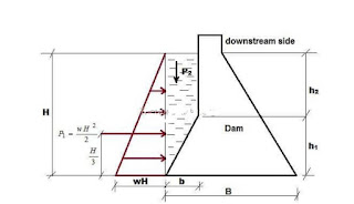
(ii) Upstream face with batter and there is no water on the
downstream
side (figure
2).
 |
| downstream side |
Here in addition to the horizontal water pressure P2 as in the
previous
case, there is vertical P2 pressure of the water. It is due to
the water column
resting on the upstream sloping side.
The vertical pressure acts on the length ‘b’ portion of the
base. This
vertical pressure is given by P2=(bxh2xw)(1/2bxh1xw)
Pressure P2 acts through the centre of gravity of the water
column resting
on the sloping upstream face.
If there is water standing on the downstream side of the dam,
pressure
may be calculated similarly. The water pressure on the
downstream face
actually stabilizes the dam. Hence as an additional factor of
safety, it may
be neglected.
II) Water pressure below the base of the
dam or Uplift pressure
enters the pores and fissures of the foundation material under
pressure. It also enters the joint between the dam and the
foundation at
the base and the pores of the dam itself. This water then seeps
through
and tries to emerge out on the downstream end. The seeping water
creates a hydraulic gradient between the upstream and downstream
side of
the dam. This hydraulic gradient causes vertical upward
pressure. The
upward pressure is known as uplift. Uplift reduces the effective
weight of
the structure and consequently the restoring force is reduced.
It is
essential to study the nature of uplift and also some methods
will have to
be devised to reduce the uplift pressure value.
 |
| Dam |
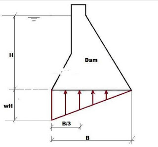
Figure 3
With reference to figure 3, uplift pressure is given by Pu=(wHxB)/2
Where Pu is the uplift pressure, B is the base width of the dam, and H
is
the height upto which water is stored.
This total uplift acts B/3 from the heel or upstream end of
the dam.
Uplift is generally reduced by providing drainage pipes or holes
in the dam
section.
The self-weight of the dam is the only largest force which
stabilizes the
structure. The total weight of the dam is supposed to act
through the
centre of gravity of the dam section in vertically downward
direction.
Naturally when specific weight of the material of construction
is high,
restoring force will be more. Construction material is so chosen
that the
density of the material is about 2.045 gram per cubic meter
2. Earthquake Forces
The effect of an earthquake is equivalent to an acceleration to the
foundation
of the dam in the direction in which the wave is travelling at
the moment.
Earthquake wave may move in any direction and for design
purposes, it is
resolved into the vertical and horizontal directions. On an
average, a
value of 0.1 to 0.15g (where g = acceleration due to gravity) is
generally
sufficient for high dams in seismic zones. In extremely seismic
regions
and in conservative designs, even a value of 0.3g may sometimes
by
adopted.
Vertical acceleration reduces the unit weight of the dam
material and that
of water is to (1-Kv) times the original unit weight, where Kv is the value
of g accounted against earthquake forces, i.e. 0.1 when 0.1g is
accounted
for earthquake forces. The horizontal acceleration acting
towards the
reservoir causes a momentary increase in water pressure and the
foundation and dam accelerate towards the reservoir and the
water
resists the movement owing to its inertia. The extra pressure
exerted by
this process is known as hydrodynamic pressure.
3. Silt Pressure
If h is the height of silt deposited, then the forces exerted by
this silt in
addition to the external water pressure, can be represented by
Rankine
formula Psilt= 1/2𝛾s KaH2 acting at h/3 from the base.
Where,
Ka= coefficient of active earth pressure of silt =
f= angle of internal friction of soil, cohesion neglected.
𝛾s= submerged unit weight of silt material.
h = height of silt deposited.
Gravity Dams Silt Pressure • It has been explained under „ Reservoir Sedimentation‟ that silt gets deposited against the upstream face of the dam. If h is the height of silt deposited, then the force exerted by this silt in addition to external water pressure, can be represented by Rankine‟s formula as: • Psilt = ½ γ subw h2 Ka and it acts at h/3 from base • Where, Ka Is The Coefficient Of Active Earth Pressure of silt • Ka = 1 - sin Ө • 1+ sin Ө • Where Ө is the angle of internal friction of Soil, and cohesion is neglected. • γ subw = Submerged unit weight of silt material • h= height of silt deposited.
4.Wave Pressure
Wave Pressure • Waves are generated on the surface of the reservoir by the blowing winds, which causes a pressure towards the downstream side. Wave pressure depends upon the wave height. Wave height may be given by the equation • Hw= 0.032 √ V.F + 0.763 – 0.271 (F) ¾ for F < 32 Km And • Hw= 0.032 √V.F for F > 32 Km • Where hw= height of water from top of crest and bottom of trough in metre. • V= Wind velocity in Km/ hr
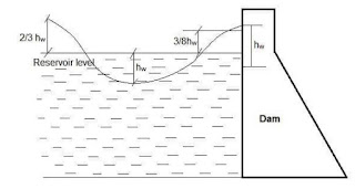 |
| Wave Pressure |
5. Ice Pressure
The ice which may be formed on the water surface of the
reservoir in cold
countries may sometimes melt and expand. The dam face is
subjected to
the thrust and exerted by the expanding ice. This force acts
linearly along
the length of the dam and at the reservoir level. The magnitude
of this
force varies from 250 to 1500 kN/sq.m depending upon the
temperature
variations. On an average, a value of 500 kN/sq.m may be taken
under
ordinary circumstances.
6. Weight of dam
The weight of dam and its foundation is a major resisting force.
In two
dimensional analysis of dam, unit length is considered




No comments:
Post a Comment
If you are getting more information from civilengineerfriend page please give your comments. Share the page information in your whatsapp group. Subscribe our page to get more information.