The structural analysis is a mathematical algorithm process by which the response of a
structure to specified loads and actions is determined. This response is measured by
determining the internal forces or stress resultants and displacements or deformations
throughout the structure.
The structural analysis is based on engineering mechanics, mechanics of solids,
laboratory research, model and prototype testing, experience and engineering judgment.
The basic methods of structural analysis are flexibility and stiffness methods. The
flexibility method is also called force method and compatibility method. The stiffness
method is also called displacement method and equilibrium method. These methods are
applicable to all type of structures; however, here only skeletal systems or framed
structures will be discussed. The examples of such structures are beams, arches, cables,
plane trusses, space trusses, plane frames, plane grids and space frames.
The skeletal structure is one whose members can be represented by lines possessing
certain rigidity properties. These one dimensional members are also called bar members
because their cross sectional dimensions are small in comparison to their lengths. The
skeletal structures may be determinate or indeterminate.
1) Direct force structures such as pin jointed plane frames and ball jointed space
frames which are loaded and supported at the nodes. Only one internal force or
stress resultant that is axial force may arise. Loads can be applied directly on the
members also but they are replaced by equivalent nodal loads. In the loaded
members additional internal forces such as bending moments, axial forces and
shears are produced.
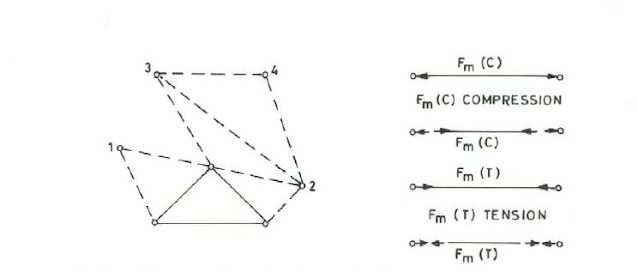
The plane truss is formed by taking basic triangle comprising of three members and three
pin joints and then adding two members and a pin node as shown in Figure 2.1. Sign
Convention for internal axial force is also shown. In Fig.2.2, a plane triangulated truss
with joint and member loading is shown. The replacement of member loading by joint
loading is shown in Fig.2.3. Internal forces developed in members are also shown.
The space truss is formed by taking basic prism comprising of six members and four ball
joints and then adding three members and a node as shown in Fig.2.4.
2) Plane frames in which all the members and applied forces lie in same plane as
shown in Fig.2.5. The joints between members are generally rigid. The stress
resultants are axial force, bending moment and corresponding shear force as shown
in Fig.2.6.
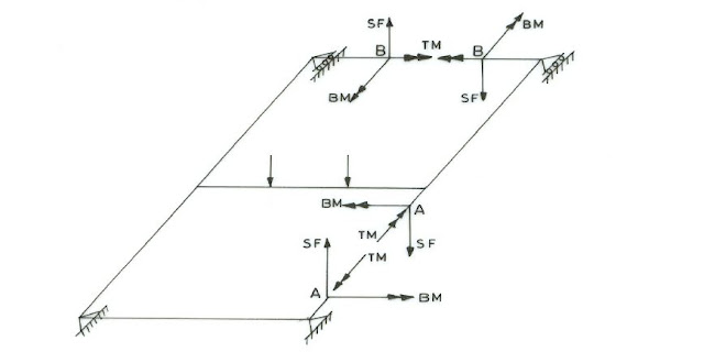
3) Plane frames in which all the members lay in the same plane and all the applied
loads act normal to the plane of frame as shown in Fig.2.7. The internal stress
resultants at a point of the structure are bending moment, corresponding shear force
and torsion moment as shown in Fig.2.8.
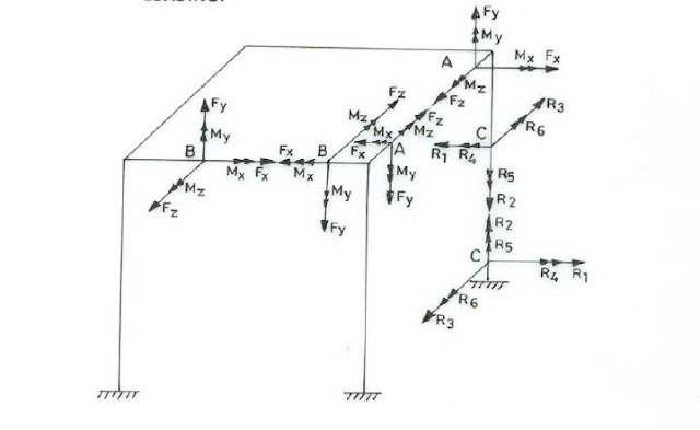
4) Space frames where no limitations are imposed on the geometry or loading in
which maximum of six stress resultants may occur at any point of structure namely
three mutually perpendicular moments of which two are bending moments and one
torsion moment and three mutually perpendicular forces of which two are shear
forces and one axial force as shown in figures 2.9 and 2.10.
3 INTERNAL LOADS DEVELOPED IN STRUCTURAL MEMBERS
External forces including moments acting on a structure produce at any section along a
structural member certain internal forces including moments which are called stress
resultants because they are due to internal stresses developed in the material of member.
The maximum number of stress resultants that can occur at any section is six, the three
Orthogonal moments and three orthogonal forces. These may also be described as the
axial force F1 acting along x – axis of member, two bending moments F5 and F6 acting
about the principal y and z axes respectively of the cross section of the member, two
corresponding shear forces F3 and F2 acting along the principal z and y axes respectively
and lastly the torsion moment F4 acting about x – axis of member. The stress resultants at
any point of centroidal axis of member are shown in Fig. 3.1 and can be represented as
follows.
Numbering system is convenient for matrix notation and use of electronic computer.
Each of these actions consists essentially of a pair of opposed actions which causes
deformation of an elemental length of a member. The pair of torsion moments cause twist
of the element, pair of bending moments cause bending of the element in corresponding
plane, the pair of axial loads cause axial deformation in longitudinal direction and the
pair of shearing forces cause shearing strains in the corresponding planes. The pairs of
biactions are shown in Fig.3.2.
Primary and secondary internal forces.
In many frames some of six internal actions contribute greatly to the elastic strain energy
and hence to the distortion of elements while others contribute negligible amount. The
material is assumed linearly elastic obeying Hooke’s law. In direct force structures axial
force is primary force, shears and bending moments are secondary. Axial force structures
do not have torsional resistance. The rigid jointed plane grid under normal loading has
bending moments and torsion moments as primary actions and axial forces and shears are
treated secondary.
In case of plane frame subjected to in plane loading only bending moment is primary
action, axial force and shear force are secondary. In curved members bending moment,
torsion and thrust (axial force) are primary while shear is secondary. In these particular
cases many a times secondary effects are not considered as it is unnecessary to
complicate the analysis by adopting general method.
4 TYPES OF STRUCTURAL LOADS
For the analysis of structures various loads to be considered are: dead load, live load,
snow load, rain load, wind load, impact load, vibration load, water current, centrifugal
force, longitudinal forces, lateral forces, buoyancy force, earth or soil pressure,
hydrostatic pressure, earthquake forces, thermal forces, erection forces, straining forces
etc. How to consider these loads is described in loading standards of various structures.
These loads are idealized for the purpose of analysis as follows.
-4-
Concentrated loads: They are applied over a small area and are idealized as point loads.
Line loads: They are distributed along narrow strip of structure such as the wall load or
the self weight of member. Neglecting width, load is considered as line load acting along
axis of member.
Surface loads: They are distributed over an area. Loads may be static or dynamic,
stationary or moving. Mathematically we have point loads and concentrated moments.
We have distributed forces and moments, we have straining and temperature variation
forces.
5 DETERMINATE AND INDETERMINATE STRUCTURAL SYSTEMS
If skeletal structure is subjected to gradually increasing loads, without distorting the
initial geometry of structure, that is, causing small displacements, the structure is said to
be stable. Dynamic loads and buckling or instability of structural system are not
considered here. If for the stable structure it is possible to find the internal forces in all
the members constituting the structure and supporting reactions at all the supports
provided from statical equations of equilibrium only, the structure is said to be
determinate. If it is possible to determine all the support reactions from equations of
equilibrium alone the structure is said to be externally determinate else externally
indeterminate. If structure is externally determinate but it is not possible to determine all
internal forces then structure is said to be internally indeterminate. Therefore a structural
system may be:
(1) Externally indeterminate but internally determinate
(2) Externally determinate but internally indeterminate
(3) Externally and internally indeterminate
(4) Externally and internally determinate
These systems are shown in figures 5.1 to 5.4.
A system which is externally and internally determinate is said to be determinate system.
A system which is externally or internally or externally and internally indeterminate is
said to be indeterminate system.
Let: v = Total number of unknown internal and support reactions
s = Total number of independent statical equations of equilibrium.


No comments:
Post a Comment
If you are getting more information from civilengineerfriend page please give your comments. Share the page information in your whatsapp group. Subscribe our page to get more information.