

Reinforcement Detailing of Simple Beams and Slabs Cantiliver and Fixed/continuous beams
Detailing of reinforcements in beams and slabs plays an important role in providing strength, durability and cost optimization. Reinforcement details of concrete beams and slabs should specify clearly about cover to reinforcement, length of reinforcement, curtailment of reinforcement, number and diameter of reinforcement to be provided.For a simply supported beam and slab, the maximum bending moment occurs at the center of the span and shear force at a distance of d/2 from the face of the support, where d is the effective depth of beam or slab. Considering this, the bending reinforcement is necessary at the center of the span and not required at the support where as shear reinforcements are required at the support.
So, it is not necessary to provide full length bending (tension) reinforcement and 50% of the reinforcement can be curtailed at suitable locations as shown in images below or can be bent upwards to provide as shear reinforcements.
Reinforcement Detailing of Simple Beams and Slabs
1. Reinforcement Details of Simply Supported Beam and Slab
As seen in figure-1 below, for a simply supported beam and slab, 100% reinforcement as per the design is provided as tension reinforcement at the mid span of the beam and slab, and 50% is curtailed at the distance of 0.08L from the center support.
 |
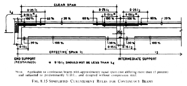
Curtailment of tension steel in simply supported beam and slab2. Reinforcement Details of Continuous Beams and Slabs
For a continuous beams and slabs, the shear force and bending moment diagrams are drawn and reinforcement details are provided based on the value of the shear force and bending moment.
As can be seen from the figure-2 below, the tension reinforcement are 100% at the mid-span of the beam and slab, while it is curtailed at the distance of 0.1 L from the center of the support at end support and 0.2L at the intermediate support. L is the effective length of the beam and slab.
The shear reinforcements are provided from the support to the distance of 0.1L from the face of support on end support and at a distance of 0.3L from the center of support at intermediate support.
 |
3. Typical reinforcement detail for concrete beam
The typical reinforcement details of a concrete beam shall indicate the number of reinforcements, diameter and length of reinforcement for both top and bottom reinforcements.

Cantilever beam
Cantilever beam is a beam by analysis point of view a beam whose far end is free without any support and fixed on the near end as in case of a diving board in which load creates shear and bending at the near end (Fixed or restrained).
This creates tension at top of the support and no tension on the farthest end (as this end is free)

fixed/continuous beam
Now for the case of a fixed/continuous beam the beam is restrained at both the ends making tension at top fibres of both ends and bottom fibres of beam at center while loading in condition.
Coming to the detailing part of both beams one can observe from the above two figures referenced from websites refered, it's a basic understanding that reinforcement mainly provided to cater the tensile needs blog the beam which concrete is weak.
Hence the main tensile reinforcement is provided at top of support of cantilever beam extending into support and l/4 length outside (The bending moment at cantilever support is considered wl^2/2 as per common notations with a uniformly distributed load). The other reinforcement is regarded as hanger bars (minimum reinforcement requirement as per codal provisions) and assumed to be not taking the critical bending moments.
For a continuous and fixed beam the main tensile reinforcement is provided at top of supports and bottom of middle of the beam (For a fixed beam the bending moments are approximately wl^2/12 (at top of fixed ends)and wl^2/24 (at bottom of center) as per common notations with a uniformly distributed load).
Shear forces will always be maximum at support locations for which we provide reinforcement in form of stirrups (spacing and no of loops depending on shear force magnitude)
Now coming to the actual question, it's said that the Cantliver beam is 12 feet long assuming there will be sufficient reinforcement at top of supporting end but, the farther end barely have sufficient reinforcement (half of reinforcement will be curtailed after l/2 or Ld by leaving required area of steel at the point generally) to counter the bending moment created by additional support making the beam cracking at the additional support there by failure (note same case with shear).
Secondly there will some minimum reinforcement at the bottom of cantliver which may or may not suffice for the bending moment at bottom originated from action of simple or fixed support at farther end. (Also there will not be any sufficient Anchorage required at the farther end for existing reinforcement.) This causes failure at mid span.


No comments:
Post a Comment
If you are getting more information from civilengineerfriend page please give your comments. Share the page information in your whatsapp group. Subscribe our page to get more information.